Tanner's Senior Project
R/C Baja
Analysis
Analyses use various methods to solve engineering problems and produce an optimal design. Engineering merit that was used for different types of analyses performed during this project consists of statics, mechanics of materials, and physics. Free body diagrams introduced in statics was used to determine different loadings and bending moments acting on each individual component of the R/C car. Mechanics of materials uses the free body diagrams from statics to analyze the stresses on the components of the R/C car. This is important to determine the different material thickness needed to ensure the success of the part. Physics introduces different equations using gravity that will be important in analyzing forces created from landing.
Analysis 1:
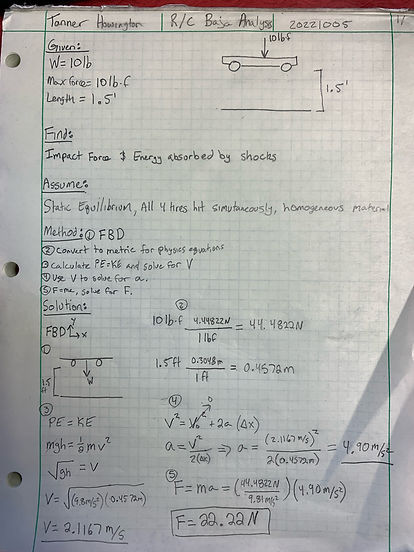
The drop test analyzes the impact force calculated after being dropped from 1.5 feet. The design requirement was that a 10lb car must be able to withstand a 1.5-foot drop to a flat surface. Using F=ma and E=PE+KE, learned in physics, the energy being absorbed by the suspension can be calculated along with the force acting on the suspension of the car. These values can be used later in determining material thickness when designing the suspension arms.
Analysis 2:
The impact test analyzes the impact force on the front of the R/C car after ramming into a wall at 20 MPH. The design requirement was that a 10lb car must be able to withstand impact at 20MPH without any critical failures happening to the car. The method for this analysis is to first convert Mi/hr to m/s, and lb to kg. After all units are converted solve for acceleration using a=v/t. Finally, knowing a, solve for impact force using F=ma
.jpeg)
Analysis 3:
The suspension arm length analysis determines the length that was needed to be used for the suspension arm according to the geometry of the relating components. The height of the front shock tower was 3 inches, the length of the purchased shocks was 115mm, and the angle of rest for the suspension arm to the shock tower is 100 degrees. The method for this analysis begins with converting the shock tower height to mm to match the length of the shock. Then, using law of sines to find angles b and c. Knowing angle b, length of B can be found using law of sine.

Analysis 4:
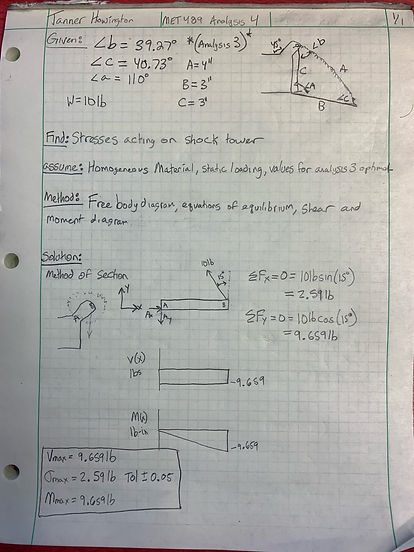
The shock tower stresses analysis determines the maximum bending stress, maximum shear stress, and maximum moment acting on the shock tower. To perform this analysis the method of sections was used. The section cut was made between the base and the arm of the shock tower. The angle from the arm to the ground was 15 degrees. Using statics and mechanics of materials, a free body diagram was created and the forces in the x and y directions were summated. Using these forces, a shear and moment diagram was created providing the maximum stresses for the shock tower section a-b
Analysis 5:
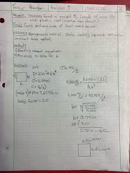
The CSA front shock tower analysis determines the cross-sectional area of the front shock tower that the stresses act on. This analysis uses the stresses calculated in analysis 4 to determine dimensions. The bending stress equation, bending stress = mc/I, can be manipulated to solve for b. The drawing used was square so it is inferred that b=h when determining I using the equation (1/12)bh3 it is known that it is equal to (1/12)b4. C is equal to (1/2)b. Rearranging the bending stress equation to solve for b will get you the dimensions of the cross sectional area. Then those values are multiplied by a safety factor of 3.0 to get the actual dimensions used. The dimensions were found as 0.5 inches for b and h due to the cross-sectional area being a square
Analysis 6:
The shock tower stresses analysis determines the maximum bending stress, maximum shear stress, and maximum moment acting on the shock tower. To perform this analysis the method of sections was used. The section cut was made between the base and the arm of the shock tower. The angle from the arm to the ground was 30 degrees. Using statics and mechanics of materials, a free body diagram was created and the forces in the x and y directions were summated. Using these forces, a shear and moment diagram was created providing the maximum stresses for the shock tower section a-b

Analysis 7:
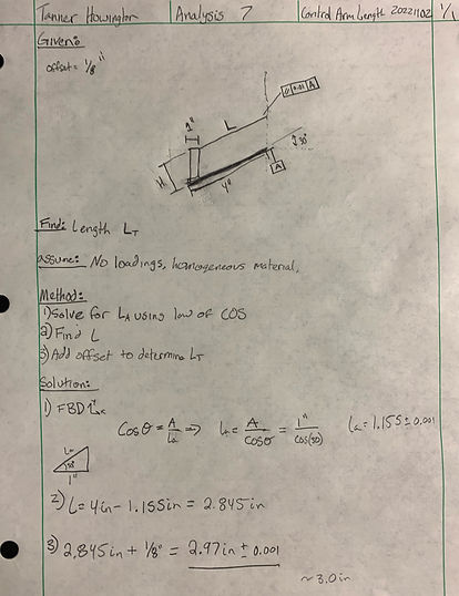
The control arm length analysis determines the required length for the upper control arm according to the geometry of the relating components. The length of the suspension arm was 4 inches, the steering knuckle had a thickness of 1 inch. The offset for the control arm was 1/8 of an inch. Using law of cosines La was determined as 1.155 inches. Subtracting 1.155 from 4 inches determines the length of L and is 2.845 inches. The last step is adding the 1/8in offset to the 2.845 inches to find total length of the upper control arm. The total length found was 2.97 inches
Analysis 8:
The CSA front shock tower analysis determines the cross-sectional area dimensions of the rear shock tower that the stresses act on. This analysis uses the stresses calculated in analysis 6 to determine dimensions. The moment acquired from analysis 6 was 19.485 lb-in. The flexural strength for ABS plastic is 11,000 psi. The bending stress equation, bending stress = mc/I, can be manipulated to solve for b. The drawing used was square so it is inferred that b=h when determining I using the equation (1/12)bh3 it is known that it is equal to (1/12)b4. C is equal to (1/2)b. Rearranging the bending stress equation to solve for b will get you the dimensions of the cross sectional area. Then those values are multiplied by a safety factor of 3.0 to get the actual dimensions used. The dimensions were found as 0.66 inches for b and h due to the cross-sectional area being a square

Analysis 9:
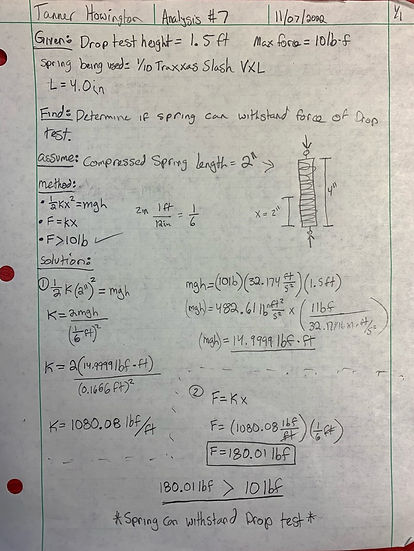
The Drop test-shock analysis determines if the spring meets the requirement of being able to withstand a drop from 1.5 feet. This analysis used knowledge in physics and basic algebra to determine the force that would cause the spring to fail. The length of the 1/10 Traxxas Slash VXL RC shock was 4in, and per the requirements the weight of the car is 10lb and the drop test is 1.5 feet. The force was calculated using equations 1/2kx2=mgh and F=kx. After calculations the determined force to cause failure in the shock is 180.01lbf. This states that the shock will withstand the drop test determining that the 1/10 Traxxas Slash VXL RC shock to be appropriate
Analysis 10:
The king pin stress analysis determines if the 1/8 diameter pin using 6061 Aluminum will fail or not. This analysis used statics and mechanics of materials to determine if the king pin will successfully hold and not fail. To do this a free body diagram shows that the pin undergoes double shear doubling the 10lbf, per the design requirement, making it 10lbf. The king pin is an important piece so a safety factor of 2 was applied making the force 40lbf. Using the equation stress=F/2A it is determined that the max stress the pin can withstand is 1629.75psi. The yield strength for 6061 aluminum is 40,000 psi. This means that the 1/8 in diameter pin will be appropriate and will not fail

Analysis 11:
The Rod-Tie length analysis determines the appropriate length for the rod tie component. The requirement that this part needs to meet is the part needs to be able to integrate with the suspension and steering components and not interfere. The part must allow the car to go straight and not deviate from a straight line more than 6 inches after 20 feet of driving straight. The analysis used addition and trig identities, specifically SOHCAHTOA, to determine the length of the overall tie rod. This resulted in a design parameter length of 7.47’’+- 0.05”.

Analysis 12:
The Rod-Tie stress analysis determines if the tie rod (1/8-inch diameter SAE 1040 cold drawn steel) will be able to withstand stress acting on component per the design requirement of the 10lb car. The analysis uses skills obtained from mechanical design to determine the critical buckling load of a beam. The Euler formula requires the following factors to complete. The modulus of elasticity, pi, end fixity, length, and diameter. Using these values plugged into Eulers formula a design requirement of not exceeding a load of 61.45lb was determined. Due to that being 6 times the weight of the car per the design requirement it is inferred that the rod-tie will not break.

Analysis 13:
The drop test failure analysis was used to determine the thickness of the flanges used in the shock tower. This analysis was used to meet the requirement of the R/C car withstanding a drop of 1.5 feet. The flanges for this analysis were analyzed as cantilever beams with a fixed-free end fixity. The first thing found was the reaction force caused by the impact of the 1.5-foot drop. Using this reaction force and dividing it by 2 the force in each individual flange was calculated. Basing off of a free body diagram, the maximum shear and moment were found on the beam. This was then used to find the maximum bending stress and transverse shear in the beam using the thickness of the flange. These values were then compared to the yield strength of the ABS plastic material used for 3D printing. It was found that the flanges failed to transverse shear. The thickness was then increased to 0.25 inches and the calculations were re-performed. This thickness was proven not to fail due to transverse shear nor bending stress so a thickness of 0.25 inches was re-designed into the shock tower part

